Additional Table Mapping
Additional mappings can be completed using data from tables of the database. That means that another table can be used to create a graphic element along the linear borehole such as the different lithology layers. When creating a new mapping, a name and a type must be selected.
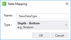
Depth - Bottom
Represents data using a start depth and an end depth.
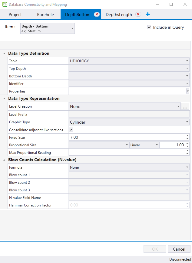
Data Type Definition: Lets you define which table and columns will be used to create the mapping.
|
Table |
The database table name used for the depth/length elements and properties. |
|
Top Depth |
The database field identifying the top depth values. |
|
Bottom Depth |
The database field identifying the bottom depth values. |
|
Identifier |
The database field which describes the item. |
|
Properties |
Any additional information from the same table that will be associated with the interval. This is optional. |
Data Type Representation: The graphic of the new mapping can be defined by a sphere, a disk, or a cylinder with a given diameter. The graphics can be stored in their respective level according to their identifier or a table name.
|
Level Creation |
The property used for level creation. None - Creates elements on the active level. Table Name - Creates a new level based on the table name. Identifier - Creates elements on separate level for each unique value in the identifier column. Numeric - Creates levels based on numeric ranges. All options work in the same way: elements are placed on the level(s) selected by the option; if a level to be created already exists (in active file or in a DGNLIB), it will not be created. Numeric option:
|
|
Level Prefix |
Lets you specify a prefix that will be added at the beginning of the level name. For example, if Geotech is specified, then each level to be created will start with Geotech_ |
|
Graphic Type |
Lets you define the graphical representation of the element. For Depth-Bottom or Depth-Length item types, a cylinder will be used. For Depth-Only item type, you can use a sphere or a disk. |
|
Consolidate adjacent like sections |
Merge identical adjacent like elements into one based on the identifier. |
|
Fixed Size |
Size of the elements (Cylinder, Sphere, Disk) that are created during the query process. It is a fixed size specified in the master's units of the model (e.g. ft or m). You can use the actual borehole diameter or a larger value to make data easier to read. |
|
Proportional Size |
This is the second method to define the size of the elements to be created when loading the data. With this method, the graphical data has a size proportional to a database field (e.g. contamination values). After selecting a field, you must select if this will be shown using a linear of a logarithmic scale, and then, a multiplier value. In linear mode, the object will have a diameter of the value stored in the database multiplied by the specified scale. In logarithmic mode, the following formula will be applied: radius = (log(proportionalReading) * ProportionalScale)/2 |
|
Max Proportional Reading |
Defines the maximum value that will be draw. If a value exceeds the Max Proportional Reading value, it will be drawn using the value specified in this field. |
Blow Counts Calculation (N-Value): Calculates the N value on the fly when loading the data. This is based on the blow count fields values.
|
Formula |
The formula to apply for the calculation on the N-value. For Imperial, the sample length unit is in inches; for Metric, the sample length unit is in meters. |
|
Blow Count |
The column containing the blow count data. |
|
N-value Field Name |
The property name in which the N-value will be displayed. |
|
Hammer Correction Factor |
The hammer correction factor used for the calculation: N60 = N-Value * (Hammer Correction Factor / 60). If not specified, the N-Value is computed as usual, from the blow counts results. |
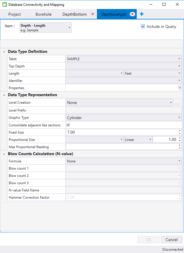
Depth Length - Represents data using a start depth and a length. (Same properties as Depth - Bottom).
Depth Only - Represents data, such as water level, using a depth. The data represented have only a point along the borehole (no length, start or end).
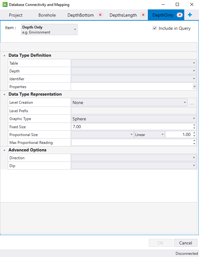
Advanced Options:
Continuous Data Reading - Represents data, such as cone penetration test (CPT). The data represented have only a point along the borehole (no length, start or end).
